Shanghai RECON BKSG Shunt Reactor Solves Capacitive Over-Compensation at EV Charging Stations
更新时间:2026-11-06 14:10:06•点击:73 • Question
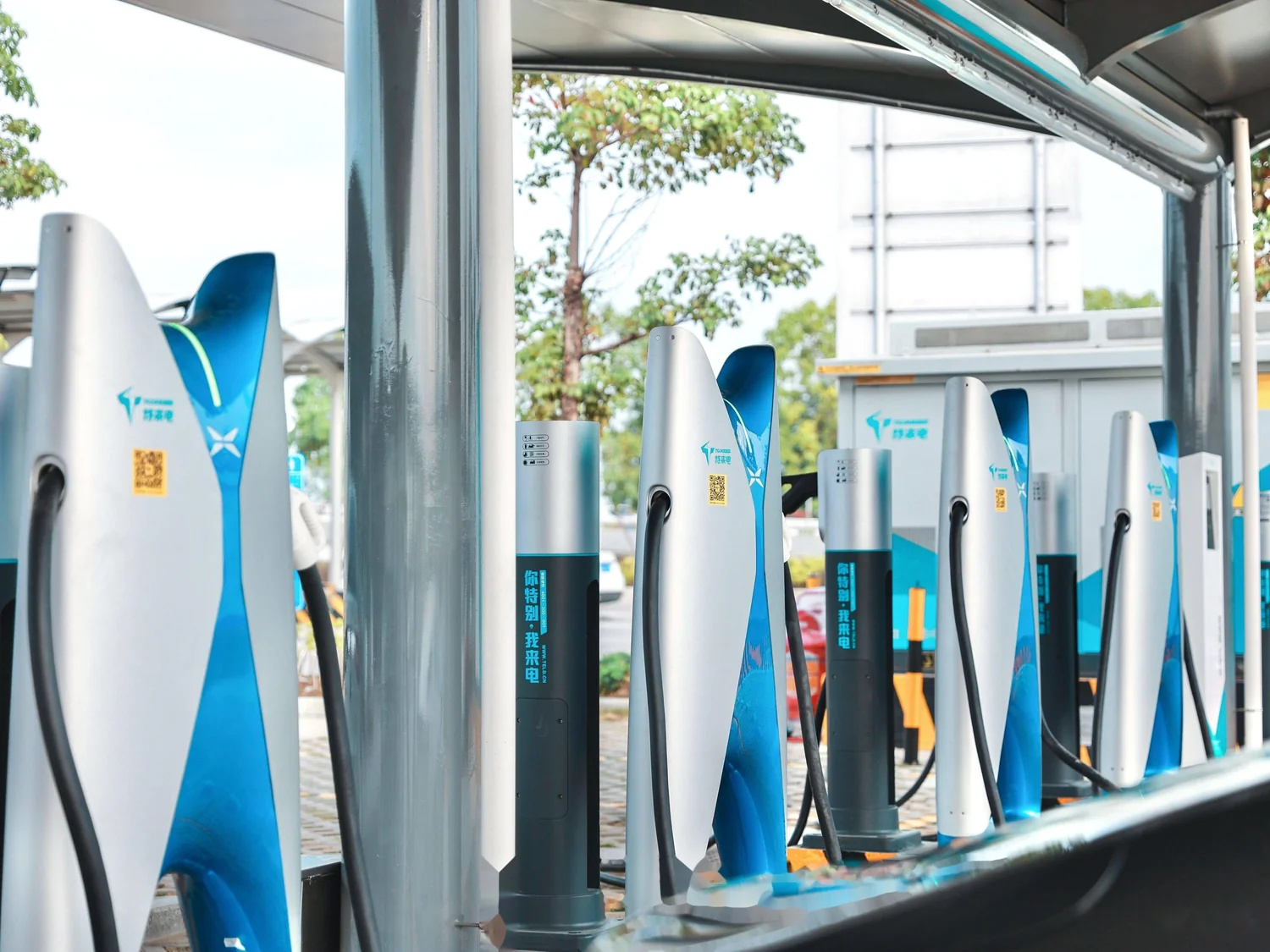
As public charging networks and dedicated fleet depots expand, a mid-sized DC fast-charging station commonly hosts a dozen or more chargers, with installed capacity exceeding 1,000 kW. Operators increasingly notice rising power factor penalty charges, higher transformer temperatures, and occasional over-voltage or over-current alarms from charger units. The root cause is often not the charger itself but the balance of reactive power, especially capacitive over-compensation during light-load periods. This article explains the mechanism, the countermeasure, and the product characteristics of the BKSG three-phase shunt reactor from Shanghai RECON.
1. From Charging Difficulty to Power Quality Difficulty
Inside a charger, rectifier modules, DC/DC conversion stages and filter units form a typical power electronic load whose reactive behaviour varies widely with output power, load factor and operating mode. When a site is equipped with fixed capacitor banks sized for full load, the compensation capacity becomes excessive as soon as traffic drops and chargers enter light-load or standby operation. This is capacitive over-compensation.
It is not a minor issue. Excess capacitive reactive power raises bus voltage, which affects stable operation of charging modules. It drives the power factor into the leading region, which is also subject to utility assessment. It also forms resonant loops with transformer and line inductance that amplify background harmonics. For operators focused on availability and maintenance cost, these are real burdens.
2. How Capacitive Over-Compensation Arises
In AC systems, reactive power divides into inductive and capacitive components. Inductive loads, such as motors and transformer magnetizing branches, absorb inductive reactive power, while capacitors generate capacitive reactive power. Compensation means using capacitive reactive power to offset inductive reactive power so that the grid-side power factor approaches unity.
However, the load factor of a charging station fluctuates sharply over the day. Morning and evening peaks may differ from midday by several times. If the compensation equipment is configured for one fixed operating point, or if switching control is too coarse, two problems appear. Under-compensation reduces power factor, increases line current and raises losses. Over-compensation sends capacitive reactive power back to the grid, lifts bus voltage and drives the power factor into the leading region. In short, compensation is not about having more capacitors, but about following the load.
3. Solution: Balancing Capacitance with Inductance
Since over-compensation means excess capacitive reactive power, the direct approach is to introduce controllable inductive reactive power to offset the surplus. The BKSG three-phase shunt reactor from Shanghai RECON plays exactly this role. Connected in parallel with the capacitor bank or the charger's filter capacitors at the busbar, it provides a stable sink for inductive reactive power. Its functions can be summarised in three layers.
First, offsetting surplus capacitive reactive power. During light-load periods when capacitor switching still leaves the site over-compensated, the shunt reactor absorbs the excess and returns the power factor to a reasonable range, avoiding reverse reactive power flow to the grid.
Second, suppressing voltage rise. Reverse capacitive reactive power raises bus voltage, while the inductive current of the shunt reactor produces a voltage drop effect. The two effects combine to stabilise bus voltage and provide a safer operating window for chargers.
Third, reducing resonance risk. With a properly selected reactance ratio, for example 5% to 6% for the 5th harmonic or 12% to 13% for the 3rd harmonic, the capacitor-reactor branch becomes inductive at the characteristic harmonic frequency. This avoids parallel resonance with system inductance and lowers the risk of damage to capacitors and charging modules.
In practice, the scheme usually combines capacitor banks, shunt reactors and an intelligent switching controller. The controller samples voltage, current and power factor in real time and switches capacity in groups according to preset thresholds, so that compensation follows the load. For existing stations with oversized capacitor banks, retrofitting shunt reactors is often more economical than replacing the entire compensation cabinet.
4. Working Principle of the BKSG Three-Phase Shunt Reactor
The BKSG series consists of a magnetic core, three-phase windings and an insulation system, with the windings connected to the three-phase busbar in star or delta configuration. When three-phase AC voltage is applied, inductive current flows through the windings according to I = U / (omega times L), and the absorbed inductive reactive power is Q = 3 times U squared / (omega times L).
Here U is the phase voltage, omega is the angular frequency (2 pi f) and L is the inductance. The compensation capacity is therefore proportional to the square of voltage and inversely proportional to inductance, making the shunt reactor a relatively stable counterweight to capacitive reactive power. In engineering practice, several reactor branches of different ratings are combined with contactors or vacuum switches to achieve stepwise capacity adjustment.
Unlike a series reactor, a shunt reactor is not connected in the load circuit but in parallel at the busbar. It does not carry load current and only supplies reactive support, so operating losses are lower and its influence on load-side voltage dip is smaller. This characteristic makes it particularly suitable for charging stations, where load fluctuates strongly and operating periods are irregular.
5. Product Performance: From Ratings to Field Reliability
The charging environment imposes specific requirements on reactors: continuous long-term operation, day-night temperature swings and outdoor humidity, a harmonic-rich background, and limited installation space. The BKSG three-phase shunt reactor is designed with these conditions in mind.
Electrical ratings. Inductance and rated current can be customised according to station capacity and capacitor configuration, with reactance ratios covering common 5% to 6% and 12% to 13% options. Rated voltage suits 400 V and 690 V low-voltage distribution levels and can be adapted to project requirements. The insulation system uses Class F or Class H epoxy resin impregnated glass fibre winding, processed by vacuum pressure impregnation and constant-temperature curing for heat and moisture resistance.
Losses and temperature rise. High-permeability cores and oxygen-free copper windings are used, with optimised winding layout to reduce stray losses. Temperature rise at rated load is kept within design limits for continuous duty in charging stations, and noise is kept at a low level for sites near residential areas.
Structure and installation. The compact dry-type design requires no oil and no maintenance, needs no oil pit or fire separation distance, and is convenient to retrofit into existing distribution rooms. Termination arrangements can be adapted for cabinet mounting or freestanding frames to shorten retrofit time.
Quality control. Every BKSG reactor undergoes dielectric tests, temperature rise tests and inductance calibration before shipment, ensuring parameter consistency in service and avoiding uneven current sharing when several units operate in parallel.
6. Typical Applications and Implementation Notes
Case one: power quality retrofit of an existing station. Where capacitor banks were oversized, leading power factor and high voltage occurred during light load. Adding shunt reactor branches and revising the switching logic bring the compensation curve in line with actual demand.
Case two: integrated solar, storage and charging sites. Photovoltaic inverters, storage PCS units and chargers coexist, so capacitive reactive power has multiple sources. BKSG shunt reactors work together with active devices to form a passive base with active fine tuning.
Case three: high-power DC fast-charging clusters. When several high-power chargers operate simultaneously, harmonic content is elevated. The shunt reactor provides inductive reactive power while its reactance ratio, together with the capacitor bank, suppresses harmonic amplification.
Three implementation points deserve attention. First, measure before selecting: use on-site power quality tests to determine the actual reactive power profile and harmonic spectrum rather than estimating from installed capacity alone. Second, leave margin in the switching strategy: set reasonable power factor limits and switching delays to prevent excessive operations. Third, coordinate with existing compensation equipment to avoid mutual interference and repeated reactive power swings.
7. Conclusion
Capacitive over-compensation at charging stations is essentially a conflict between fixed compensation and fluctuating load. The value of the BKSG three-phase shunt reactor lies not in complexity but in a direct physical approach: absorbing capacitive reactive power with inductance, providing a stable, reliable and adjustable counterweight. For operators facing power quality issues, moving from one-time sizing to load-following compensation is often more effective than simply adding capacity.
The technical parameters described above are general design ranges. Specific projects should be determined according to on-site power quality test data and distribution system conditions. Performance descriptions refer to technical principles, and actual results depend on site conditions.
About Shanghai RECON Electric Power Technology Co., Ltd.
Shanghai RECON Electric Power Technology Co., Ltd. focuses on the development and manufacturing of reactors and power quality improvement equipment. Its product range covers reactor accessories for variable frequency drives, high-voltage series and shunt reactors, over-compensation reactors for charging stations, SVG connection reactors and APF active filters. The manufacturing base is located in Shanghai, with customised design and on-site technical support available. Website: www.recon.com.cn
Recommended Reading
-
Shanghai RECON BKSG Shunt Reactor Solves Capacitive Over-Compensation at EV Charging Stations
2026-11-06 14:10:06•73 次
-
RECON Shanghai Ruikang All-Copper 10kV HV SVG Reactors Delivered
2026-07-25 11:58:49•3200 次
-
Shanghai RECON 7% Series Reactor Solves Harmonic Capacitor Failure
2026-07-23 22:25:13•3307 次
-

Air-Core Shunt Reactor: The Invisible Guardian of Grid Safety
2026-05-04 19:41:17•5573 次


